
When designing thermal management systems for high-power electronic devices, selecting liquid cooling is only the first step. The more critical engineering decision lies in choosing the right liquid cold plate manufacturing process. How a cold plate is fabricated directly impacts heat dissipation efficiency, structural reliability, and overall product lifespan.
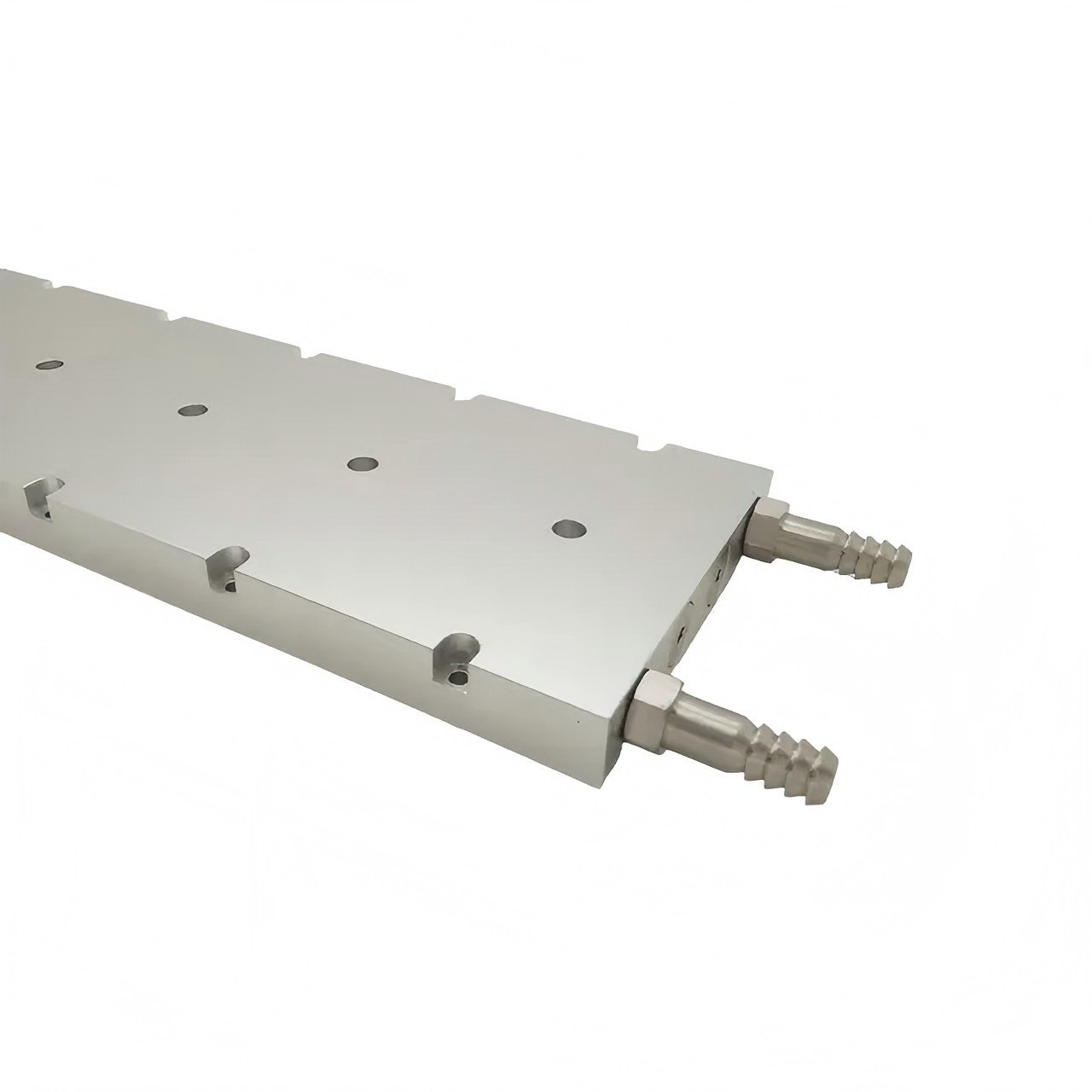
Currently, two primary manufacturing methods dominate the high-performance cooling market: Vacuum Brazing and Friction Stir Welding (FSW).
Deciding between a vacuum brazed and an FSW liquid cold plate isn’t about finding a single “superior” technology. Instead, it’s about matching the manufacturing process to your specific thermal load, internal flow path, pressure limits, and production requirements.
Here is a breakdown of the structural differences, performance trade-offs, and design considerations to help you select the ideal process for your system.
1. Why the Manufacturing Process Matters
In any liquid cooling loop, the cold plate serves as the physical bridge between the heat source and the coolant fluid. If that bridge is flawed, thermal efficiency drops and risk rises.
+-------------------------------------------------------------------+
|                        Heat Source (IGBT / AI GPU)                |
+-------------------------------------------------------------------+
                                  │ (Thermal Interface)
+-------------------------------------------------------------------+
|                     Liquid Cold Plate Surface                     |
|  ┌─────────────────────────────────────────────────────────────┐  |
|  │              Internal Coolant Flow Channels                  │  |
|  └─────────────────────────────────────────────────────────────┘  |
+-------------------------------------------------------------------+
                                  │ (Heat Absorption)
+-------------------------------------------------------------------+
|                         Coolant Fluid Out                         |
+-------------------------------------------------------------------+
The manufacturing process governs two key parameters:
-
Internal Channel Geometry: Determines whether you can integrate dense 3D micro-channels or are restricted to simpler, linear paths.
-
Structural & Seal Integrity: Dictates whether the cold plate can endure sustained pressure over a multi-year operational lifecycle without leaking.
When pushing thermal boundaries to reduce overall thermal resistance ($R_{th}$), engineers rely on customized ports, strict form factors, and optimized flow distribution. Choosing a process that misaligns with these goals increases the risk of uneven flow, severe local hotspots, and coolant leaks.
2. Vacuum Brazing: Precision & Intricate Internal Paths
Vacuum brazing joins metal components together inside a specialized high-temperature vacuum furnace.
          [ Top Plate (Machined Channels) ]
─────────────────────────────────────────────────────
  - - - - Layer of Brazing Filler Metal - - - - - -
─────────────────────────────────────────────────────
        [ Bottom Cover / Base Plate ]
                         │
                         ▼  Vacuum Furnace Heating
        ┌───────────────────────────────────┐
        │ Capillary Action Bonds Entire     │
        │ Assembly Surface Uniformly        │
└───────────────────────────────────┘-
Top and base plates (typically CNC-machined with detailed internal channels) are aligned with a thin layer of brazing filler metal placed between them.
-
The assembly is placed into a vacuum furnace and heated until the filler metal melts, flowing into every joint interface via capillary action.
-
Because oxygen is completely evacuated from the furnace chamber, metal oxidation is prevented without requiring chemical fluxes—a process known as flux-free bonding.
Key Advantage: Unmatched Design Freedom
Because the component is heated uniformly across its entire mass, engineers can incorporate complex 3D internal channels, high-density fin arrays, and winding fluid routing paths. This uniform, flux-free bonding keeps internal channels clean and allows heat to be transferred directly from severe hotspots with minimal thermal resistance.
3. Friction Stir Welding (FSW): Solid-State Structural Strength
Friction Stir Welding is a solid-state joining process focused on high mechanical strength and robust structural integrity.
              Rotating FSW Tool
                   │    │
                   │    │
                   ▼    ▼
           ┌──────────────────┐
           │ Friction Zone    │
    ───────┴──────────────────┴───────
      Plate A  ║ Plasticized ║  Plate B
               ║ Metal Seam  ║
──────────────────────────────────-
A rapidly rotating tool bit is plunged directly into the seam between two overlapping or abutting metal parts.
-
The resulting friction generates localized heat, softening (plasticizing) the metal without melting it.
-
As the tool moves along the joint, it mechanically mixes the plasticized metal to form a continuous solid-state forge weld.
Key Advantage: Mechanical Durability & Large Area Coverage
Because the base metal stays below its melting point, FSW minimizes thermal distortion, porosity, and structural weakening common in traditional fusion welding. It excels at joining larger assemblies while maintaining high joint strength. However, because the rotating tool requires a clear, continuous path, FSW is best suited for cold plates with regular, straightforward flow geometries.
4. Head-to-Head Comparison
| Feature | Vacuum Brazing Cold Plate | FSW Liquid Cold Plate |
|---|---|---|
| Joining Method | High-temperature metallurgical bonding in vacuum | Solid-state mechanical friction mixing |
| Channel Capability | Complex, intricate 3D internal geometries & micro-fins | Regular, straightforward, linear or simple curved paths |
| Thermal Design Freedom | Very High (supports high-density localized cooling) | Moderate (constrained by tool clearance paths) |
| Structural Characteristics | Excellent surface-wide leak prevention & sealing | Outstanding mechanical strength and structural rigidity |
| Primary Use Cases | High heat flux, tight spaces, strict thermal targets | Large surface areas, heavy-duty structural components |
| Target Applications | AI Servers, HPC, Power Electronics, Aerospace | EV Battery Trays, Industrial Drives, Standard IGBTs |
5. Matching the Process to Your Application
                     IS YOUR HEAT FLUX / SPACE EXTREME?
                                     │
                    ┌────────────────┴────────────────┐
                    │                                 │
                   YES                                NO
                    │                                 │
                    ▼                                 ▼
         [ VACUUM BRAZING ]                     [ FSW PROCESS ]
    • Intricate 3D Micro-channels         • High Structural Rigidity
    • Ultra-compact Enclosures            • Large Surface Area Trays
    • Target Hotspots (AI / HPC)          • EV Battery Enclosures
Case A: High-Power Electronics & Power Conversion
High-power IGBT modules, inverters, and industrial drives emit immense thermal loads over continuous duty cycles. Utilizing vacuum brazing allows cooling channels to run immediately adjacent to heat generation zones, maximizing heat transfer while keeping the overall footprint compact.
Case B: Space-Constrained Data Center & AI Equipment
In AI servers and High-Performance Computing (HPC) chassis, internal volume is tightly constrained, while processor heat flux continues to rise. Vacuum brazing enables micro-channel arrays inside ultra-thin plates, delivering high heat extraction directly at chip hotspots without exceeding chassis height restrictions.
6. Mitigating Procurement Risks through Engineering Support
Selecting the right process is only half the equation; verifying the design prior to production is essential to prevent operational failures.
Key risks in liquid cooling—such as internal fluid bypass, localized overheating, and joint leaks—are mitigated using engineering simulation and validation tools:
-
CFD (Computational Fluid Dynamics): Simulates internal flow velocities, verifies pressure drop ($\Delta P$), and eliminates stagnant flow zones across critical heat sources.
-
FEA (Finite Element Analysis): Evaluates structural strain and deflection under maximum operating pressure to verify seal stability.
-
Precision Process Control: Advanced vacuum brazing requires precise furnace temperature profiling and post-process helium mass spectrometer leak testing to guarantee zero-leak operation.
  [ Design Concept ]
          │
          ▼
  [ CFD Simulation ]  ──► (Optimize Flow & Heat Transfer)
          │
          ▼
  [ FEA Analysis ]    ──► (Validate Structural Integrity)
          │
          ▼
  [ Precision Manufacturing & Helium Leak Test ]
Conclusion & Engineering Consultation
At Xuyuan Precision, we provide end-to-end liquid cooling manufacturing services—from initial thermal simulation and rapid prototyping to full-scale mass production. Whether your application requires the thermal performance of a vacuum brazed cold plate or the structural durability of an FSW assembly, our engineering team helps optimize your design for manufacturability, performance, and long-term reliability.
Contact jason@xyjmrk.cn to discuss your liquid cooling requirements or submit your CAD models for a complete thermal and manufacturability evaluation.
Frequently Asked Questions (FAQ)
1. What does “flux-free bonding” mean in vacuum brazing?
Traditional brazing uses chemical fluxes to clean and prevent metal oxidation during heating. Vacuum brazing operates in an oxygen-free vacuum furnace, eliminating the need for flux entirely. This leaves internal liquid channels free of corrosive chemical residues that could otherwise contaminate the coolant loop.
2. Can FSW cold plates be used for high-density AI servers?
While FSW produces strong welds, it is generally unsuited for high-density AI server modules. AI processors demand intricate micro-channel geometries directly over concentrated hotspots. FSW is constrained by the mechanical tool path, making vacuum brazing the preferred choice for dense server cooling architectures.
3. Why is vacuum brazing better for custom internal channels?
During vacuum brazing, the filler alloy melts and draws into the joint interfaces via capillary action across the entire surface simultaneously. This allows engineers to design complex, multi-directional flow paths and fine internal structures without being restricted by tool access.
4. How do costs compare between Vacuum Brazing and FSW?
Cost depends on component size, internal geometry, and production batch sizes. Vacuum brazing requires specialized furnace equipment and cycle times, which can drive higher unit costs for simple designs. However, for high-performance thermal requirements, it is often the most cost-effective path to achieve required heat dissipation within tight volume constraints.
5. How are leak risks controlled during manufacturing?
Leak prevention relies on both pre-production simulation and post-production testing. Structural stress is verified through FEA under peak operating pressures, while finished cold plates undergo pressure proof testing and high-sensitivity helium leak detection to verify hermetic seal integrity.
Post time: Aug-06-2026


